Name of Standard: Bell Prover national standard of gas flow in the range of 0.5 m3/h to 280 m3/h
Code designation: ECM 140-1/00-008
Year of publication: 2017
Department: dpt. 5012 CMI OI Praha
Guarantor: Ing. Tomáš Valenta
Number of CMC lines to be provided: 1
| Range of flows | Uncertainty U (k=2) |
| 0,5 m3/h to 280 m3/h | 0,07 % of the measured value |
A basic schematic of the Bell Prover is shown in Figure 1, a photograph is shown in Figure 2. The lower vessel is a welded cylindrical steel vessel into which another cylindrical liner is inserted. The resulting inter-cylinder space contains Shell Morlina 5 low viscosity oil. The second vessel consists of a cylindrical bell with the bottom facing upwards, the walls of which are partially immersed in oil and which is suspended from a steel cable. The bell sits on an air cushion which is created by a filling fan. The oil in the lower vessel thus acts as a hydraulic lock.

Figure 1 - Schematic picture of the Bell Prover
A steel profile support structure is fixed to the rigid structure of the lower outer vessel, on which other Bell Prover equipment is mounted. Precise vertical movement of the measuring bell is ensured by guide rods and ball bearings. The bearings are mounted in brackets at the top of the bell. The bearing housings of the rope guide pulleys are mounted on the support structure. The rope transmission, together with the weight system, ensures that the buoyancy forces acting on the bell, which is immersed in oil, are compensated for and that a constant pressure is maintained under the bell during the measuring cycle. The weight system consists of two weights. One weight, which ensures a constant oil level in the intermediate cylinder space, is attached to a steel cable and is immersed in the oil reservoir forming a connected vessel with the intermediate cylinder space of the lower vessels. A second weight, which compensates for the buoyancy force, is suspended from a wire rope which is routed through an eccentric disc.
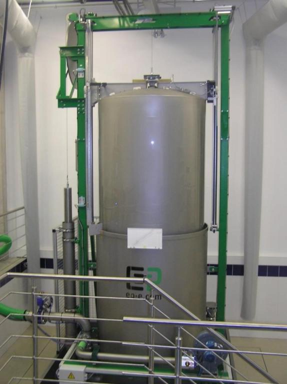
Figure 2 - Photograph of the Bell Prover
An air pipe is fed into the inner cylinder of the lower vessel. A filling pipe, connected via a shut-off valve to the fan, enters the air pipe at the bottom of the lower vessel. When the fan is switched on and the shut-off flap is opened, pressurised air passes through the filling line and the bell rises to the upper position.
The air line is connected to another shut-off valve on the outside of the lower vessel. By opening the flap on the air line upstream of the measuring line, air is forced by the weight of the bell into the gauge under test. If the pressure drop of the gauge is greater than the overpressure generated by the bell weight, then a vacuum pump located at the end of the measuring line in the adjacent room can be switched on. All shut-off valves on the Bell Prover are pneumatically operated. A side shut-off flap is incorporated in the measuring line in front of the gauge under test, which is opened whenever the bell's downward motion is rapidly stopped at the end of the test, allowing air to be drawn into the space between the bell and the gauge under test, thereby preventing damage to the gauge under test, which might be susceptible to a sudden stop. The air flow can be regulated by a manual damper and two valves located on the measuring line between the gas meter under test and the bell.

Figure 3 - Bell Prover Control Panel
All testing on the Bell Prover is controlled and managed by a personal computer equipped with the appropriate software (Figure 3).
At the start of the test, the shut-off valve on the measuring line opens, causing air to be forced out of the bell and into the gauge under test. The bell begins to sink downwards. After the downward movement of the bell has been established, the position of the bell is read on two incremental rulers at a certain pulse from the gas meter or after a certain volume has been displaced (when testing gauges without pulse output, e.g. nozzles with critical flow regime). At the final predefined pulse from the gas meter or after displacement of a predefined volume of air, the final bell position is read and the two shut-off valves on the measuring line are closed at the same time. The fan is then automatically switched on and the bell is pushed to its initial position. Before the next test, a film of oil must be allowed to run off the inner walls of the bell, which reduces the inner diameter of the bell. From the known geometric measurement of the bell, and from the measured length of the bell drop, the pressure under the bell and in the gas meter under test, the temperature under the bell and in the gas meter under test during the test and the volume recorded by the gas meter under test, it is possible to calculate the error with which the gas meter under test recorded the volume of air leaked. The exact calculation formula is given in work procedure 512-MP-C103.
In the rising mode, two pressure regulators are used to adjust the inlet pressure of the air entering the unit from a 2.7 m pressure vessel. The principle of the tests is then similar, but with a greater uncertainty of measurement due to the film of oil that adheres to the inner wall of the bell.
During one test, all measured quantities are read from the auxiliary measuring instruments at least once per second. At the end of each test, the average of all these measured values is calculated and the starting and ending value is recorded. The temperature inside the bell is determined from an electronic thermometer and under the bell, where homogeneity is ensured by a small fan. The temperature of the air in the gas meter under test is also measured by an electronic thermometer in the measuring line near the meter under test. The absolute pressure in the bell is measured directly by an electronic pressure gauge to which a tube is led from the inside of the bell. The differential pressure between the bell and the gauge under test is also measured by an electronic pressure gauge, usually from the pressure outlet "pr " or upstream of the critical flow nozzle. The displacement of the bell is measured by two incremental rulers which are located at the ground guide rods. The average value of the bell displacement measured by these two rulers is used to calculate the error of the gas meter under test.
The volume displaced by the bell is calculated according to the procedure described in document 512-MP-C103. The geometric evaluation of the bell was carried out at the Physikalisch-Technische Bundesanstalt (PTB) and is described in the document Calibration certificate of Bell Prover type PTB-D1400, calibration mark 14-14066.
Geometrické vyhodnocení zvonu bylo provedeno v Physikalisch-Technische Bundesanstalt (PTB) a je popsáno v dokumentu Calibration certificate of Bell Prover type PTB-D1400, calibration mark 14-14066.